
Journal of Cardiobiology
Download PDF
Research Article
*Address for Correspondence: Ernst Wellnhofer, M.D., Ph.D., Deutsches Herzzentrum Berlin, Augustenburger Platz 1, 13353 Berlin, Germany, Tel: ++49 30 45932400; Fax: ++49 30 45932500; E-mail: Wellnhofer@dhzb.de
Citation: Wellnhofer E, Krügel M, Nietsch M, Combé V, Sommer M, et al. Validation of a Device for High Fidelity Correction of Pressure Signals from Fluid-Filled Systems by Harmonic Analysis. J Cardiobiol. 2013;1(2): 6.
Copyright © 2013 Wellnhofer E, et al. This is an open access article distributed under the Creative Commons Attribution License, which permits unrestricted use, distribution, and reproduction in any medium, provided the original work is properly cited.
Journal of Cardiobiology | ISSN: 2332-3671 | Volume: 1, Issue: 2
Submission: 03 October 2013 | Accepted: 31 October 2013 | Published: 04 November 2013
Reviewed & Approved by: Dr. Elaine M Smolock, Aab Cardiovascular Research Institute, University of Rochester Medical Center, USA
A C++ Programm was developed for simultaneous management of
The correction is performed in the frequency domain by complex multiplication with a correction data set, which is the inverse of the transfer function of the system. The crucial point of the correction algorithm is an appropriate segmentation and trend correction of the signal [22,23].The core of the corrector is a digital signal processor (ADSP-21065L) with four 16 bit analog to digital and four 12 bit digital to analog converters for four independent galvanically separated pressure channels. The housing is water-proof and may be disinfected easily. A clear layout, which comprises an alpha-numeric display and 8 touch pads, and a well arranged logical menue assure easy handling. The device communicates with the computer by a fast RS 232 interface with an FTDI driver. The data format of the packets can be provided by the author. We used in-house software in C++ for batch testing and signal acquisition and MATLAB™ (Mathworks Inc., Natick, USA) for batch analysis and visualization of results. Further technical and security information on the device is provided by author and in the appendix.
1According to IEC 60601-2-34-2000 limits of accuracy for invasive pressure monitors are both ±4% AND ±4 mmHg or 0.5 Pa. In case of low pressure, e. g. right atrial pressures a few mmHg are equivalent to a high percentage. On the other side if pressures are well above 100 mmHg or dP/dt max the usage of percentage is more appropriate. The given criteria were based on unpublished prior tests.
An example of correction of an overdamped system is presented in Figure 4. Figure 4A shows the transfer function and Figure 4b demonstrates the result.
Systolic and diastolic pressure errors and errors of maximal and minimal dP/dt were the four variables in a multifactorial ANOVA model with Bonferroni correction. The model was adjusted for natural frequency and damping coefficient of the transfer system as covariates. Investigated factors were correction (yes, no) and type of signal with relation to frequency content (left ventricular, left ventricular sampled at double frequency, aortic, pulmonary arterial, right ventricular, right atrial, right ventricular sampled at double frequency). The model (710 cases /16 cells) was significant for all variables (F-values ranged from 19-25). The observed power was 1 at a 0.05 significance level. Regression analysis for covariates showed a significant impact of natural frequency on pressure errors (t = −3.85, p < 0.001 diastole, t = −1.97, p = 0.05 systole) and a significant impact of damping on dP/dt errors errors (t = 2.46, p = 0.014 minimum of dP/dt, t = 2.207, p = 0.028 maximum of dP/dt). This means that the results of correction are not completely independent from the transfer function of the corrected system. The significances are borderline, however, with exception of the impact of natural frequency on diastolic error. The relative importance of the effect of correction, type of signal and interaction of these factors is reflected by the differences in magnitude of the respective F-values in Table 1. As expected, correction is not independent of the frequency content of the pressure signal. The F-values of this factor and its interaction with correction are much lower than the F-values of correction itself, however. This means that the impact of the the frequency content of the signal on correction is significant but of minor effect.
Validation of a Device for High Fidelity Correction of Pressure Signals from Fluid-Filled Systems by Harmonic Analysis
Ernst Wellnhofer1*, Martin Krügel2, Mathias Nietsch2, Volker Combé1, Michael Sommer3 and Eckart Fleck1
- 1Deutsches Herzzentrum Berlin, Augustenburger Platz 1, 13353 Berlin, Germany
- 2Eurotronics GmbH, Weißenfelser Straße 67, 04229 Leipzig, Germany
- 3MedServ GmbH, Eisenacher Straße 72, 04155 Leipzig, Germany
*Address for Correspondence: Ernst Wellnhofer, M.D., Ph.D., Deutsches Herzzentrum Berlin, Augustenburger Platz 1, 13353 Berlin, Germany, Tel: ++49 30 45932400; Fax: ++49 30 45932500; E-mail: Wellnhofer@dhzb.de
Citation: Wellnhofer E, Krügel M, Nietsch M, Combé V, Sommer M, et al. Validation of a Device for High Fidelity Correction of Pressure Signals from Fluid-Filled Systems by Harmonic Analysis. J Cardiobiol. 2013;1(2): 6.
Copyright © 2013 Wellnhofer E, et al. This is an open access article distributed under the Creative Commons Attribution License, which permits unrestricted use, distribution, and reproduction in any medium, provided the original work is properly cited.
Journal of Cardiobiology | ISSN: 2332-3671 | Volume: 1, Issue: 2
Submission: 03 October 2013 | Accepted: 31 October 2013 | Published: 04 November 2013
Reviewed & Approved by: Dr. Elaine M Smolock, Aab Cardiovascular Research Institute, University of Rochester Medical Center, USA
Abstract
Fluid-filled systems are generally used for invasive pressure measurements in cardiology, anesthesiology and intensive care medicine. Wave reflection and attenuation cause considerable signal distortion. The article presents the in vitro validation of a new commercially available device for the correction of distortion of pressures.Methods: The fluid-filled system consisted of different standard catheters, which were connected to the transducer using standard kits and alternatively lines of different length allowing a systematic variation of resonance frequency (6 Hz - 30 Hz). Enhanced damping was simulated by interposition of a damping device (R.O.S.E.) in the line. Correction data were calculated from a measurement of the transfer function. Pressure was generated by a pressure generator (Biotek) from tip-pressure signals collected from different patients for left ventricular, aortic, right ventricular, pulmonalis and right atrial pressures. The corrected and the uncorrected pressure signals were compared with the reference pressure as to their impact on diastolic and systolic error and dP/dt.
Results: A total of 360 signals (minimum length 1 min) were evaluated. Mean systolic (diastolic) errors in uncorrected signals ranged from 10.3±11.5 mmHg (6.9±6.7 mmHg) in left ventricles to 1.2±1.1 mmHg (0.7±0.4 mmHg) in pulmonary arteries. Mean systolic errors in corrected signals ranged from 2.3±1.2 mmHg (2.3±1.2 mmHg) in left ventricles to 0.6±0.4 mmHg (0.6±0.3 mmHg) in pulmonary arteries. Mean systolic errors of dP/dt in uncorrected (corrected) signals ranged from 636±463 mmHg/s (76±71 mmHg/s) in left ventricles to 67±40 mmHg/s (15±8 mmHg/s) in pulmonary arteries. The error of RA pressures was < 1 mmHg even in uncorrected pressure signals. Severe damping (rose) was associated with significantly elevated errors.
Conclusions: Elevated standard deviations of errors in uncorrected signal reflect the unpredictable variability of pressure distortion. The corrector consistently achieves acceptable accuracy for absolute systolic and diastolic errors and dynamic distortion reflected by dP/dt in all tested systems and signals. It does not deteriorate accuracy in any case.
Keywords
Harmonic analysis; Pressure signal correction; Invasive hemodynamics
Introduction
Venous and arterial catheterization have become routinely used standard techniques predominantly for diagnostic purposes in cardiology and for monitoring in anesthesiology and intensive care medicine [1-3]. Commonly fluid filled lines with interposed cocks providing facilities for infusion and/or injection of various solutions, medication or contrast agent are used to connect the catheter to a pressure transducer transforming the mechanical signal into an electrical signal. Wave reflection and attenuation may cause considerable signal distortion in such distributed systems [4-12]. Mechanical optimization of the fluid filled system [11,13-15] by changing the configuration is limited due to restrictive boundary conditions imposed by the needs of the user and the available components. Early approaches to correct distorted pressure tracings are based on Frank’s theory [4], later refined by Hansen and Warburg [16,17]. Using some simplifying assumptions the mechanical part of the sytem may be treated as a damped forced oscillation (second order system) and may be characterized by its resonance frequency and damping coefficient. A correction was usually done by optimal damping below resonance frequency with an analog compensator [5]. This procedure was rather complicated and the developement of catheters with high-fidelity pressure transducers integrated in the tip of the catheter (or recently a pressure guide-wire) was a more successful approach solving this problem [18]. However, the expensiveness and fragility of such tip devices as well as calibration problems (drift) and handling (additional adapter interface) are limiting the use of tippressure devices in a routine setting. Filtering is a common approach used in monitoring systems to correct the amplitude overshoot. A device automatically compensating resonant artifacts by use of a notch filter was proposed by Brower et al. [19]. But filtering increases phase distortion and may delete frequency information. A more refined method using specially designed families of digital filters was proposed for automatic real-time correction of pressure waveforms 1992 [20]. The method assumes an underdamped second-order dynamic system and the design of the filters is based on a sampled signal input possibly limiting the use of this method. Lambermont et al. proposed a method for correction of pressure wave distortion in the time domain based on the principle that a fluid-filled catheter recording system is considered as an underdamped dynamic system fully characterized by its natural frequency and damping ratio [21]. They use the first and second time derivative of pressure, which are rather sensitive to artifacts and noise.We present the validation of a commercially available correction device (corrector) based on an algorithm in the frequency domain [22,23].
Methods
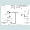
Test setupThe test set-up is schematically shown in Figure 1. The signal is fed into the system by a pressure generator. The input (signal at transducer 1 in Figure 1) and the output (signal at transducer 2 in Figure 1) of the fluid filled system are measured. Both signals are fed into the corrector. In the test set-up the output was connected to channel 1. Corrected and original pressures were sampled. The input or reference signal was connected to channel 2. At channel 2 only the original signal was sampled.
General settings for signal acquisition
Data were sampled at a rate of 500 Hz and a resolution of 16 bit. A high-precision amplifier without filter was used for conversion of pressure signals from the microvolt to millivolt range. Zero offset adjustment was performed before every measurement.
Acquisition of correction data
For all in vitro-tests a reference transfer-function was evaluated. A comb-function with equal frequency distribution (0.125 Hz grid) was fed into the system by a pressure generator (see Figure 1). The input (signal at transducer 1 in Figure 1) and the output (signal at transducer 2 in Figure 1) of the fluid filled system were measured, sampled and digitized at a rate of 1000 Hz with a resolution of 16 bit per sample bypassing the corrector (upper inputs in the A/D board in Figure 1). The transfer-function was calculated by taking the complex-valued ratio of output to input. From the transfer function the correction data set was calculated by taking the complex-valued inverse function. This correction data set was transferred from the computer to the corrector by use of the RS232 interface.
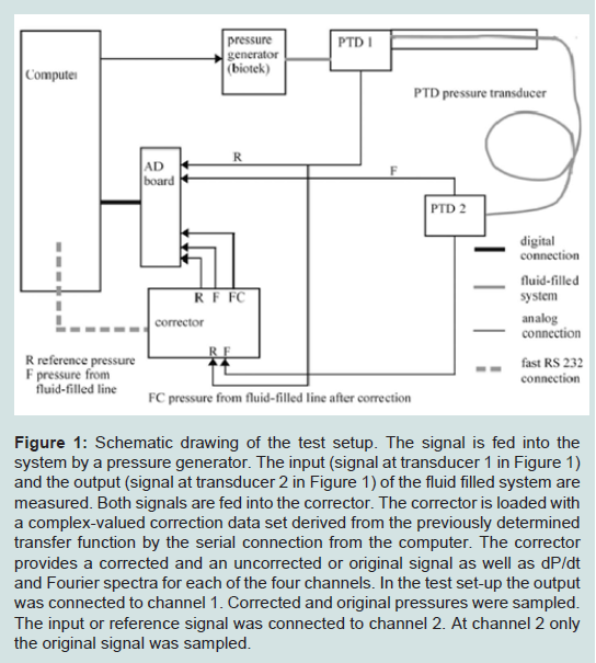
Figure 1: Schematic drawing of the test setup. The signal is fed into the system by a pressure generator. The input (signal at transducer 1 in Figure 1) and the output (signal at transducer 2 in Figure 1) of the fluid filled system are measured. Both signals are fed into the corrector. The corrector is loaded with a complex-valued correction data set derived from the previously determined transfer function by the serial connection from the computer. The corrector provides a corrected and an uncorrected or original signal as well as dP/dt and Fourier spectra for each of the four channels. In the test set-up the output was connected to channel 1. Corrected and original pressures were sampled. The input or reference signal was connected to channel 2. At channel 2 only the original signal was sampled.
• visual control,
• online calculation of dP/dt
• online calculation of beatwise error statistics
• storage of measurements and dP/dt (1-2 min)
• storage of acquisition parameters (header)
• storage of statistics
Corrector
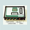
The corrector is a stand-alone device interposed between transducer and monitoring system and/or workstation for further signal processing (see Figure 2) manufactured by MedServ GmbH, Eisenacher Straße 72, 04155 Leipzig, Germany. Technical notes are given in an appendix.
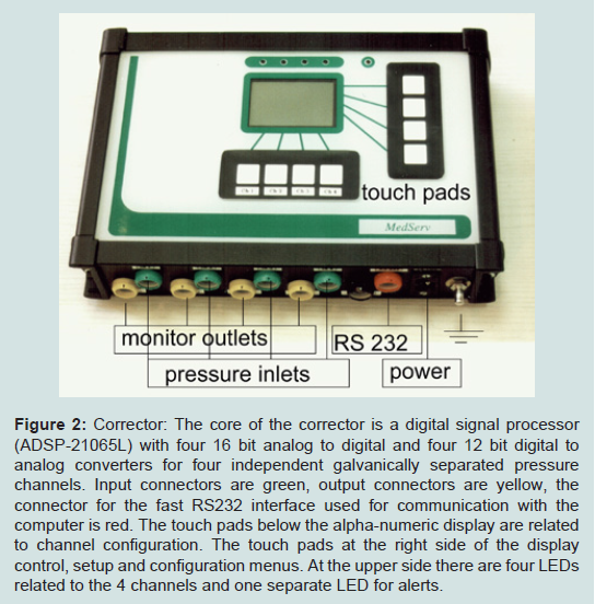
Figure 2: Corrector: The core of the corrector is a digital signal processor (ADSP-21065L) with four 16 bit analog to digital and four 12 bit digital to analog converters for four independent galvanically separated pressure channels. Input connectors are green, output connectors are yellow, the connector for the fast RS232 interface used for communication with the computer is red. The touch pads below the alpha-numeric display are related to channel configuration. The touch pads at the right side of the display control, setup and configuration menus. At the upper side there are four LEDs related to the 4 channels and one separate LED for alerts.
The device provides four channel simultaneous online correction of blood pressure. The corrected and the uncorrected/original pressure are provided as analog signals or digital signal by a fast RS232 interface. Additionally dP/dt and Fourier Spectra are provided by the RS232 interface, which also serves as communication port e.g. to load external correction data sets or flash bios updates. In this investigation the corrector is loaded with a complex-valued correction data set derived from the previously determined transfer function.
We tested a sample of tip pressure signals sratified with respect to diagnosis (see below), rhythm (sinus rhythm, atrial fibrillation, extrasystoles) and site of circulation (right atrium, pulmonary wedge pressure, pulmonary artery, right ventricle, left ventricle, aorta). Each signal was tested with all kits (see below). The kits were chosen to include optimal and worst case szenarios.
Tested signals: A representative sample of clinical pressure measurements was evaluated.
High pressure:
Left ventricular pressures (5 samples):
Tip-recording from a patient with severe mitral stenosis and atrial fibrillation.
Tip-recording from a patient with hypertrophic obstructive cardiomyopathy and ventricular extrasystoles.
Tip-recording from a patient with acute infarction.Tip-recording from a patient with coronary artery disease.
Tip-recording from a patient with hypertrophic obstructive cardiomyopathy and ventricular extrasystoles re-sampled at double frequency for simulation of tachycardia.
Arterial pressures (5 samples):
Tip-recording of aortic pressure from a patient with hypertrophic obstructive cardiomyopathy.
Tip-recording of aortic pressure from two patients with acute infarction.
Tip-recording of aortic pressure with 20 Hz filter (pressure-wire Endosonics) from a heart transplant recipient.Synthetic peripheral arterial signal generated by the pressure generator (Biotek signal 9).
Low pressure:
Pulmonary arterial pressures (3 samples):
Tip-recording from a patient with chronic heart failure, elevated pulmonary pressures and increased respiratory baseline oscillation.
Tip-recording from a patient with moderate coronary artery disease, normal pulmonary pressures and minor respiratory baseline oscillation.
Tip-recording from a patient with atrial fibrillation, borderline pulmonary pressures and moderate respiratory baseline oscillation.
Right ventricular pressures (4 samples):
Tip-recording from a patient with chronic heart failure, elevated pulmonary pressures and increased respiratory baseline oscillation.
Tip-recording from a patient with moderate coronary artery disease, normal pulmonary pressures and minor respiratory baseline oscillation.
Tip-recording from a patient with atrial fibrillation, borderline pulmonary pressures and moderate respiratory baseline oscillation.
Tip-recording from a patient with moderate coronary artery disease, normal pulmonary pressures and minor respiratory baseline oscillation re-sampled at double frequency for simulation of tachycardia.
Right atrial pressures (3 samples):
Tip-recording from a patient with chronic heart failure, elevated pulmonary pressures and increased respiratory baseline oscillation.
Tip-recording from a patient with moderate coronary artery disease, normal pulmonary pressures and minor respiratory baseline oscillation.
Tip-recording from a patient with atrial fibrillation, borderline pulmonary pressures and moderate respiratory baseline oscillation.
Comb-signal pressure (mean value 40 mmHg)
Tested systems:
High pressure correction was evaluated with 18 different systems:
A 3F Pigtail catheter, a 7 F Pigtail catheter (7 F PIG Cordis®) and a Swan-Ganz catheter (TDK 5127 Becton Dickinson®) were combined with different lengths of fluid filled lines in such a way that resonance frequencies near 7, 12 and 20 Hz were attained with each catheter. Each system was evaluated with and without an additional damping device (R.O.S.E.) [15]. Thus we covered the range of clinicallly relevant resonance frequencies. The different lumina of the catheters and the damping devices assured that the damping covered the range of realistic clinical fluid filled systems.
Low pressure correction was evaluated with 16 different clinically relevant systems:
A 20 G 5cm arterial canula, a Swan-Ganz catheter (TDK 5127 Becton Dickinson®), a 22 G 20 cm single lumen central venous catheter (Becton Dickinson®) and a 7 F 20 cm triple lumen central venous catheter (Becton Dickinson®) were combined with two different pressure kits (Becton Dickinson® 682017 and 685175). Again each system was tested with and without damping device (R.O.S.E) [15].
In a subset (7 F pigtail with tubing, Becton Dickinson TDK5127 Swan Ganz catheter with Kit 682017) 20 high and 20 low-pressure signals were serially assessed after 1 week to evaluate repeatibility.
Statistics: Errors are expressed by deviation of the measured or corrected pressure from the reference signal. For low pressures (< 40 mmHg) absolute errors in mmHg, for high pressures (≥ 40 mmHg) and the maxima and minima of dP/dt relative errors (variance coefficients) are given. Significance of improvement was evaluated by comparing the respective errors of the measurded and the corrected signal by a paired T-test. Criteria for acceptable correction/accuracy were established before the beginning of the study1:
• Low pressure error < 2 mmHg
• High pressure error < 7 %
• dP/dt error < 15%
Multivariate factorial analysis of variance was performed to assess the impact of factors significantly influencing the correction and their interactions. SPSS™ satistical software was used for this purpose. For assessment of repeatibility mean difference, standard deviation of mean difference and T-values and P-values of the paired T-test are presented.
1According to IEC 60601-2-34-2000 limits of accuracy for invasive pressure monitors are both ±4% AND ±4 mmHg or 0.5 Pa. In case of low pressure, e. g. right atrial pressures a few mmHg are equivalent to a high percentage. On the other side if pressures are well above 100 mmHg or dP/dt max the usage of percentage is more appropriate. The given criteria were based on unpublished prior tests.
Results
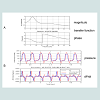
A total of 360 signals (minimum length 1 min) were evaluated. The error of RA pressures was low even in uncorrected signals. Mean systolic and diastolic as well as DP/dt errors decreased significantly. The device reduces errors below 7% in systole and 2 mmHg in diastole and improves dynamic modeling (dP/dt) for all tested transfer functions including most clinically relevant fluid filled systems (dP/dt error < 15%). Thus acceptable accuracy according to our predifined criteria was attained. The decrease in error was highly significant (p < 0.001) for systolic and diastolic as well as DP/dt errors in all tested systems for all tested signals. Correction did not increase any error in comparison to tip-pressure measurents in any combination of test signal with test system.An example of correction of an underdamped system is presented in Figure 3. Figure 3A shows the transfer function and Figure 3B demonstrates the result.
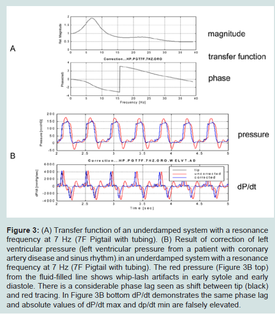
Figure 3: (A) Transfer function of an underdamped system with a resonance frequency at 7 Hz (7F Pigtail with tubing). (B) Result of correction of left ventricular pressure (left ventricular pressure from a patient with coronary artery disease and sinus rhythm) in an underdamped system with a resonance frequency at 7 Hz (7F Pigtail with tubing). The red pressure (Figure 3B top) from the fluid-filled line shows whip-lash artifacts in early sytole and early diastole. There is a considerable phase lag seen as shift between tip (black) and red tracing. In Figure 3B bottom dP/dt demonstrates the same phase lag and absolute values of dP/dt max and dp/dt min are falsely elevated.
An example of correction of a Gabarith™ system [14] (Becton Dickinson TDK5127 Swan Ganz catheter with Kit 682017) is presented in Figure 5. Figure 5A shows the transfer function and Figure 5B demonstrates the result. 
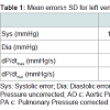
The overall results for the absolute errors of pressure signals with relevant distortion (no right atrial pressures) are summarized in Table 1. The most striking feature in this table is the reduction of the dP/dt errors. This reflects the improvement of dynamical accuracy.
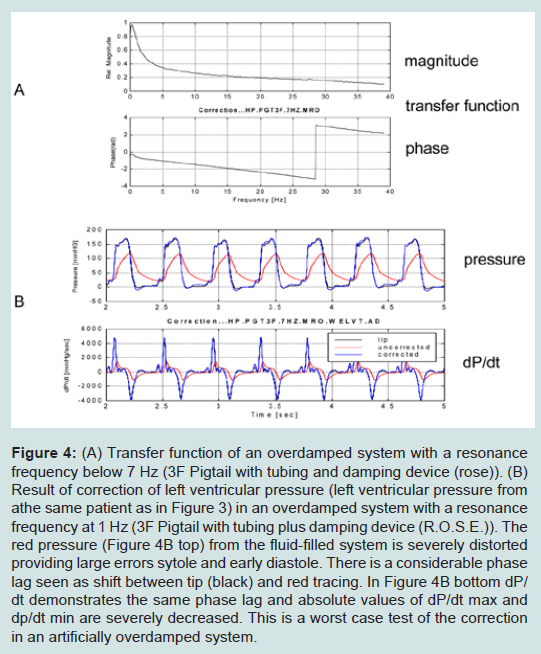
Figure 4: (A) Transfer function of an overdamped system with a resonance frequency below 7 Hz (3F Pigtail with tubing and damping device (rose)). (B) Result of correction of left ventricular pressure (left ventricular pressure from athe same patient as in Figure 3) in an overdamped system with a resonance frequency at 1 Hz (3F Pigtail with tubing plus damping device (R.O.S.E.)). The red pressure (Figure 4B top) from the fluid-filled system is severely distorted providing large errors sytole and early diastole. There is a considerable phase lag seen as shift between tip (black) and red tracing. In Figure 4B bottom dP/dt demonstrates the same phase lag and absolute values of dP/dt max and dp/dt min are severely decreased. This is a worst case test of the correction in an artificially overdamped system.
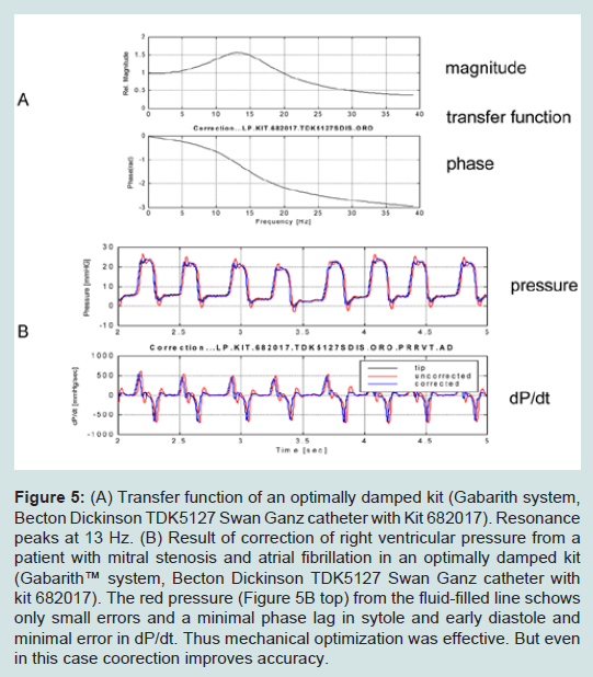
Figure 5: (A) Transfer function of an optimally damped kit (Gabarith system, Becton Dickinson TDK5127 Swan Ganz catheter with Kit 682017). Resonance peaks at 13 Hz. (B) Result of correction of right ventricular pressure from a patient with mitral stenosis and atrial fibrillation in an optimally damped kit (Gabarith™ system, Becton Dickinson TDK5127 Swan Ganz catheter with kit 682017). The red pressure (Figure 5B top) from the fluid-filled line schows only small errors and a minimal phase lag in sytole and early diastole and minimal error in dP/dt. Thus mechanical optimization was effective. But even in this case coorection improves accuracy.
• Severe damping (rose) was associated with significantly elevated errors even with empirically determined data sets. Severe damping should be avoided.
• Patient signals resampled at double frequency for simulation of tachycardic signals demonstrated a slightly but significantly elevated error even after correction. The error remained within the limits of 7% systolic and 2 mmHg diastolic pressure difference.
• Error was elevated in the comb-signal tests probably due to difficult segmentation of the signal. There are no beats in a comb-signal, which provide naturally defined segments.
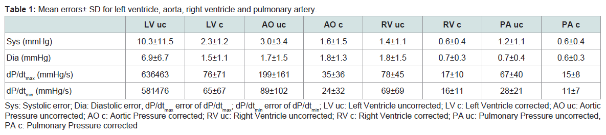
Table 1: (A) Mean errors ± SD for left ventricle, aorta, right ventricle and pulmonary artery.
The difference in percent systolic error in between two serial measurements was 1.7±3%. The difference in absolute diastolic error in between two serial measurements was −0.3±0.6 mmHg. The difference in percent dP/dtmax error in between two serial measurements was −4±6%. The difference in percent dP/dtmin error in between two serial measurements was −3±8%. These differences were not significant (dP/dtmax, dP/dtmin and absolute diastolic error) or borderline (percent systolic error P=0.0311). These differences are small and may be related to minor differences in the test setup (transfer system, zeroing, electrical noise etc.), which cannot be completely excluded in a serial test of a complex system.
Discussion
Though attempts using harmonic analysis for assessment and correction of periodic pressure signals have been made already some decades ago, they have been rather disappointing [24]. Pressure signals are not strictly harmonic and vary with respect to basic cycle length. Analysis of appropriate segments, e.g. one heart beat, with detrending and adaptive Fourier analysis, e.g. by zero-padding or different length, is crucial [22]. Modern digital signal processors allow an effective implementation of digital correction of pressure signals distorted by the transfer systems currently in clinical use. The validation of the tested device demonstrated a reproducible and accurate correction of pressure signals with different frequency content from a representative variety of liquid filled systems. The device performs A/D conversion and digital differentiation of the pressure signals in addition to correction on up to four channels simultaneously. It is easy to handle and complies with security standards in intensive care and operative medicine. It is interposed between pressure transducers and monitoring system and/or digital workstation.Clinical implications
Measurement of pressures by liquid-filled systems is currently the standard invasive pressure measurement. Since the systems are generally used for infusion and intervention in addition to pressure monitoring stop-cocks and manifolds are interposed in the liquidfilled system. Rather long lines are in use in order to preserve some mobility of the patient and the hospital staff. Microbubbles and depositions of fibrin or blood in the system or external compression of the system at some site may occur. As a result the systems demonstrate a rather low natural frequency and variable damping. The overlap of the frequency band of the transfer function with frequency band of the signal depends on the frequency content of the signal, which may be subject to gross changes, e.g after injection of catecholamines. As a result the effective distortion error varies depending on the frequency content of the signal even if the transfer function of the liquid filled system is stable. The clinician must be aware that all measured pressures apart from mean pressure are likely to be wrong under such conditions. And the size of the error is not constant or limited and may not be evaluated in a clinical setting. Digital statistics of pressure values apart from mean pressure are worthless. Valuable indicators of cardiac function as dP/dt or relaxation time and of compliance as pressure wave forms may not be used because of their enhanced sensitivity to distortion. The corrector improves this situation considerably. The enhanced accuracy limits the errors and allows quantitative statistical and mathematical evaluation of pressures. Well established physiological information hitherto restricted to tip-measurements as the analysis of systolic and diastolic ventricular function or of cardiovascular coupling may gain enhanced clinical importance [25-28].
Limitations
Any algorithm analyzing and correcting a segment of a pressure tracing results in a short correspondent time lag, in our case 2 sec or about 2 heart beats, visible in the on-line display of the corrected signal by comparison to a reference signal as the ECG. Additional display of the uncorrected signal or concomitant shift of correlated signals (e.g. ECG) are currently available approaches to this principal draw-back, which is however not limited to the presented method.The device provides a modular but yet not integrated solution in monitoring and patient information system. This limitation can be principally abolished in future. As a result of the concept of modularity the corrector does not provide any application. Clinical applications for more accurate blood pressure recordings determine the commercial fate of such a device and have to be developed and tested. In a clinical setting it is difficult and sometimes impossible to perform an empirical determination of the transfer function. The commonly used flush-test is poorly standardized and may provide hazardous information [29]. It has been successfully used however to monitor and adapt for drifts or changes of the transfer function by Hori et al. [20]. More sophisticated methods as neural nets may be employed to monitor damping or other changes in the sytem [30]. An automatic system identification and continuous calibration based on the statistical propperties of the Fourier spectra of the measured (uncorrected) signals has been developed at our institution. It is currently validated and will be published in near future.
Summary
The corrector consistently achieves acceptable accuracy for absolute systolic and diastolic errors and dynamic distortion reflected by dP/dt in all tested systems and signals.It does not deteriorate accuracy in any case.
Acknowledgements
The project was sponsored by a grant of the Sächsisches Staatsministerium für Wirtschaft und Arbeit (project number 4932/753). Becton Dickinson provided transducers, one-way materials and the pressure generator (Biotek). I would like to express my special thanks to Dr. Peter Werner for his expert advice and his encouraging engagement in the promotion of this project.References
- Hug J, Oswald H, Wellnhofer E, Fleck E (2001) Herzkatheterdiagnostik. In: Hombach V, ed. Interventionelle Kardiologie, Angiologie und Kardiovaskularchirurgie Technik Klinik Therapie. Stuttgart: Schattauer 3-32.
- Jalonen J (1997) Invasive haemodynamic monitoring: concepts and practical approaches. Ann Med 29: 313-318.
- Mueller HS, Chatterjee K, Davis KB, Fifer MA, Franklin C, et al. (1998) ACC expert consensus document. Present use of bedside right heart catheterization in patients with cardiac disease. American College of Cardiology. J Am Coll Cardiol 32: 840-864.
- Frank O (1903) Kritik der elastische Manometer. Z Biol 44: 445-613
- Fry DL (1960) Physiologic recording by modern instruments with particular reference to pressure recording. Physiol Rev 40: 753-788.
- Fry DL, Mallons AJ, Noble FW (1957) An evaluation of modern pressure recording systems. Circ Res 5: 40-46.
- Hipkins SF, Rutten AJ, Runciman WB (1989) Experimental analysis of catheter-manometer systems in vitro and in vivo. Anesthesiology 71: 893-906.
- Albrecht DM, Ragaller M (1996) Beurteilung der Fehlergrößen von Druckmesssystemen und deren klinische Relevanz. AINS 31: 2-5.
- Billiet E, Colardyn F (1996) Technische Grundlagen der Bludruckmessung und mögliche Fehlerquellen. AINS 31: 6-8.
- Mc Donald DA (1990) Measuring principles of arterial waves. In: Nichols WW, O'Rourke MF, McDonald R, eds. Blood Flow in Arteries. London: Edward Arnold 143-195.
- Gardner RM (1981) Direct blood pressure measurement--dynamic response requirements. Anesthesiology 54: 227-236.
- Shinozaki T, Deane RS, Mazuza JE (1980) The dynamic responses of liquid-filled catheter systems for direct measurements of blood pressure. Anesthesiology 53: 498-504.
- Mendler N, Wiederholt B, Feil G (1988) Blutdruckmessung mit einweg-Sensoren: kriterien für den entwurf von Meßsystemen. Kardiotechnik 11: 104-110.
- Billiet E, Colardyn F (1998) Pressure measurement evaluation and accuracy validation: the Gabarith test. Intensive Care Med 24: 1323-1326.
- Kleinman B, Powell S (1989) Dynamic response of the ROSE damping device. J Clin Monit 5: 111-115.
- Hansen AT (1949) The theory for elastic liquid-containing membrane manometers. Special part. Acta Physiol Scand 19: 333-343.
- Hansen AT, Warburg E (1949) The theory for elastic liquid-containing membrane manometers. General Part. Acta Physiol Scand 19: 306-332.
- Nichols WW, Walker WE (1974) Experience with the Millar PC-350 catheter-tip pressure transducer. Biomed Eng 9: 58-60.
- Brower RW, Spaans W, Rewiersma PA, Meester GT (1975) A fully automatic device for compensating for artifacts in conventional catheter-manometer pressure recordings. Biomed Eng 10: 305-310.
- Hori J, Saitoh Y, Kiryu T, IIjima T (1992) Automatic correction of left-ventricular pressure waveform using the natural observation method. IEICE Trans Inf Syst E75-D: 909-915.
- Lambermont B, Gerard P, Detry O, Kolh P, Potty P, et al. (1998) Correction of pressure waveforms recorded by fluid-filled catheter recording systems: a new method using a transfer equation. Acta Anaesthesiol Scand 42: 717-720.
- Wellnhofer E, Combe V, Oswald H, Fleck E (1999) High fidelity correction of pressure signals from fluid-filled systems by harmonic analysis. J Clin Monit Comput 15: 307-315.
- Wellnhofer E (2001) Correction of blood pressure measurements in invasive liquid-filled systems. Patent: PCT/DE98/03486[WO 99/26531].
- Krovetz LJ, Jennings RB Jr, Goldbloom SD (1974) Limitation of correction of frequency dependent artefact in pressure recordings using harmonic analysis. Circulation 50: 992-997.
- Krayenbuehl HP, Rutishauser W, Wirz P, Amende I, Mehmel H (1973) High-fidelity left ventricular pressure measurements for the assessment of cardiac contractility in man. Am J Cardiol 31: 415-427.
- Laskey WK, Kussmaul WG (1987) Arterial wave reflection in heart failure. Circulation 75: 711-722.
- Mason DT, Braunwald E, Ross J Jr, Morrow AG (1964) Diagnostic value of the first and second derivatives of the arterial pressure pulse in aortic valve disease and in hypertrophic subaortic stenosis. Circulation 30: 90-100.
- Latham RD, Rubal BJ, Sipkema P, Westerhof N, Virmani R, et al. (1988) Ventricular/vascular coupling and regional arterial dynamics in the chronically hypertensive baboon: correlation with cardiovascular structural adaptation. Circ Res 63: 798-811.
- Billiet E, Colardyn F (1992) Hazardous information from bedside fast-flush device test for fluid-filled pressure monitoring systems. Angiology 43: 988-995.
- Prentza A, Wesseling KH (1995) Catheter-manometer system damped blood pressures detected by neural nets. Med Biol Eng Comput 33: 589-595.